4W 1.7GHz 8CH Ultra Light FPV VTX 25.85g Low Latency for Racing Drone
I. Product Appearance

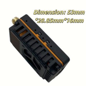
II. Product Dimension
III. Specifications
1 1.7GHz 8CH: 1680MHz-1960MHz
2. Max power: 4W (25mW/2000mW/4000mW, adjustable)
3. Input voltage: DC 7V-36V, supporting 2-8S battery input
4. Antenna connector: SMA Mother seat inner hole
5. Smart audio: IRC Tramp
6. Heat-dissipating method: aluminum alloy shell, heat sink&fan
7. Hole spacing: 20mm*20mm/ø2mm
8. Dimension: 53mm*28.85mm*16mm
9. Weight: 25.85g.
IV. Function Introduction
1. Channel indicator: Red LED
2. Band indicator: Blue LED
3. Power indicator: Green LED
4. Band & Channel changer button
5. Power changer button
6. 1.0 6P Power connector
V. Control Method and LED Indicator
1. Button 4 is used to switch band and channel; every time when button 4 is pressed for a short time to switch to the next channel, the red LED 1 will flash, 1.2.3.4.5.6.7.8 in turn. The operation can be cyclic; see the following diagram for details!
2.Button 5 is the power adjustment button. Each short press switches the power by one level, cycling through the four levels of 25mW, 2000mW, and 4000mW. The green LED is the power indicator light, with the following states as shown in the figure below: 25mW flashes once, 1000mW flashes twice, 2000mW flashes three times, and 4000mW flashes four times. Press and hold for 3 seconds to enter pit mode, with the green light staying on. See the figure below for details!
Note: This image transmission device has a temperature protection function. When the temperature of the image transmission device exceeds 100°C, the transmission power of the image transmission device will be reduced by one level. If the temperature remains above 100°C, the transmission power will be reduced by another level until it reaches the lowest power level (25mW). At this point, the temperature of the image transmission device will decrease. When the temperature drops to 95°C, the transmission power will return to the originally set power level.
VI. Frequency Table
VII. Illustrate of 6P 1.0 Wiring
Wiring Table:
VIII. Notice for Use:
1. The VTX must be installed with space to ensure that the air convection around the module to ensure that the module heat dissipation; otherwise, the module overheating protection start, reduce the power to transmit, or even shut down the power to transmit.
2. It is recommended that before turning on the power, to ensure that the correct voltage range, positive and negative poles are correct, so as not to burn components.
3. It is recommended that before turning on the power, make sure that the RF RF output has been installed antenna, which can extend the life of the module.
4. Please read the instruction manual before use, so that you can correctly wire and extend the module service life.